 |  |  |  |  |  |  |
|---|---|---|---|---|---|---|
 |  |  |  |  |  |  |
 |  |  |  |  |  |  |
 |  |  |  |  |  |  |
 |  |  |  |  |  |  |
 |  |  |  |  |  |  |
 |  |
Click on a picture in the gallery above to see a full resolution image, or to navigate manually. For more images, scroll down
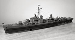
USS Gearing (DD-710)
Atlantic Ocean,1945
Why this ship?
Growing up as son of a Navy officer, I spent many of my young years around Gearing, Sumner and Fletcher-class destroyers, which were at the time the backbone of the Brazilian Navy. This was a different time with respect to security, so my friends and I used to just hang around the harbour, and fish from the shadow of these ships. So, there is some sentimental value attached. The ships I knew were all post-FRAM, but I have not found any available injection mould models representing these versions (a fact that still surprises me, as I am sure they would be a huge success). Thus, I decided to start with the "as built" versions.
What was added
-
The only extra items that needed to be purchased were railings. This kit comes with a comprehensive photoetch set, but, perhaps a bit strangely (considering the effort the manufacturer obviously put into it), no railings were included. I used a mix of 1/350 railing from L'Arsenal (with safety nets) and generic railing left over from building the Bismarck. The latter were sometimes cut to create specialised items of railing which are suggested by photos of early Gearing class ships (e.g. around the torpedo tubes).
-
Rigging was done with a mix of fine surgical silk, human hair, and black Caenis thread (for thicker, intermediate and fine items, respectively).
-
I used tungsten wire to substitute the styrene parts representing the aerials sticking from the aft stack, and the jackstaff. Both of these appeared too thick as provided in the kit, and kept breaking during the build. I also used a small piece of tungsten to create a flagstaff (not included in the kit).
Notes and lessons learned
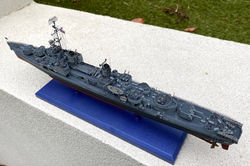
This was a challenging kit from beginning to end. I mean this in a positive way: it is complex because it strives to be precise. The price one pays for this precision is to have to deal with many very, very small pieces, many combining polystyrene and photoetch, which need to be fitted in a limited space (see below, the completed Gearing side by side with the Tamiya Bismarck, both 1/350).
Building the Gearing involves fitting a larger number of small parts in a much smaller space, in comparison with the Bismarck.
Having said that, this kit is worth every penny. The fit between parts is fantastic, there is no flash at all, and the parts are represented precisely, both in shape and size. The sprues include spares which can be saved for future projects like doors, hatches, guns and even a set of torpedo tubes.
In summary, this is not a kit for novices, for the impatient, or for the ham-fisted. Don't try to rush it, and the results will be worth it. Just make sure you get yourself a pair of very fine tweezers before you get started. You will be dealing with parts smaller than 1 mm, pretty much from the first day (see construction photos below).
One feature that is apparent in contemporary photos of ships of this class, but not captured in the kit, are joints between hull panel lines, which become visible from some angles (see here and here). I tried to create a suggestion of these without going overboard, by running a fine pacer in appropriate places over the painted hull, before the final sealing coat (Vallejo matt varnish, diluted with water and a bit of flow improver).
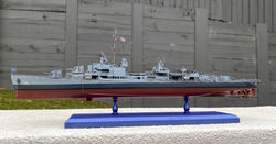
Most of this model was painted with Mr. Color lacquers (diluted for airbrush 40:60 with Mr. Color levelling thinner). According to the instructions, two of the main colours require mixing paint: the 20-B deck blue that dominates most horizontal surfaces (a mix of Mr. Color 2, 3, 14 and 72), and the 5-H haze grey which covers most of the rest (Mr. Color 74, 2 and 3). I have no preconception of what deck blue looks like, so just followed the instructions. I also dutifully mixed the haze grey according to instructions, but after one coat realised that it looks (to my eyes) just like the Mr. Color 337 (greyish blue) that I used in the Super Étendard Modernisé. So, this is what I used for all subsequent coats. For the lower hull, I went with equal parts of Tamiya XF-7 (flat red) and XF-9 (hull red), diluted with X-20, to to create something similar to what I remember seeing in dry docked destroyers many times. In the end, I am satisfied that the colours I see in my model resemble the ones I see in the picture below (the USS Kidd, a contemporary ship preserved as a museum).
Colour comparison: a real USN World War II Fletcher class destroyer, preserved as a museum ship, vs. the 1/350 Gearing. The colours seem close enough to my eye.
And a few more pictures...
Click on a picture in the gallery above to see a full resolution image, or to navigate manually
Problems circumvented
-
I only had one real problem with this kit, which was to do with the decals representing the anti-slip walkways. They are beautifully printed, but much to my surprise, don't play well with the traditional Microset and Microsol steps. This is the first time I came across this situation. I applied these decals after the usual steps: surface primed (Alclad black), painted (Mr. Color lacquers), and covered with an airbrushed layer of floor polish. But they kept bubbling up every time I applied a layer of Vallejo varnish (satin) to seal them in place. At least 3 times I had to re-flatten them with cotton tips, reapply the Microset/ Microsol, and let it dry overnight. Despite the frustration, the decals are very sturdy, so none ended up torn, despite the mistreatment.
The instructions are reasonably clear, but there is some room for improvement:
-
Step 2 of the construction is where it is recommended that you apply most of the decals representing anti-slip walkways. Separate diagrams are presented for the placement of these decals on the main and upper decks, and on top of the pilot house. However, keep in mind that decal 25 does not go on any of these (unlike all others decals illustrated in step 2). Instead, it goes on the elevated platform with twin Bofors mounts, located between the bridge and the fore stack, which is not assembled until step 3. There is real potential for a mistake here, due to unclear instructions. The image below shows the correct placement.
-
By the way, resist the temptation to leave the anti-slip walkway decals to be applied later. It will be pretty hard to manoeuvre them in place once you are past step 2, where a myriad of small parts is glued to the decks (pictures 3 and 4 of my construction photos show the stage of my build when these decals were applied).
- In step 3 there is an error in the instruction for placement of part B32, which should fit in a hole in the aforementioned AA gun platform (part B22). Not, as the instructions would let you believe (see here), next to the starboard twin 40 mm Bofors mount.
- The propeller guards are provided as photoetched parts, and the kit comes with helpful plastic parts to help bend these appropriately. However, these parts are found in sprue F (parts F1 and F2), not in sprue D, as the instructions would make you believe.
- Finally, the instructions would have you install the 4 photoetch ladders connecting the upper deck to the pilot house in step 7, pretty much at the end, after the main mast is installed. This would give you very limited access, and probably cause a lot of things to break. Do yourself a favour, and glue them in place as part of step 3.
And a final set of pictures.


Construction photos

Dragon USS Gearing; list of parts needed to build one Oerlikon 20 mm mount

Dragon USS Gearing; some of the small sub-assemblies, after base coat with Alclad

Dragon USS Gearing: railing installed. "Only" the main mast and rigging remaining to do.
Dragon USS Gearing; list of parts needed to build one Oerlikon 20 mm mount
Click on a picture in the gallery above to see a full resolution image, or to navigate manually
1. There are a lot of small parts. One of the first things to do is to assemble 10 Oerlikon 20 mm mounts. Here are the parts required to build one of these - 7 plastic parts and 2 photo etch...
2. The first may days of the build are occupied with assembling a lot of small parts, combining plastic and photo etch.
3. Finally, for a change, painting and applying decals to the main deck.
4. Upper deck assembled and painted, 5" turrets dry-fitted in position.
5. Dry fitting the stacks, showing the photoetch parts included in the kit. The gun platform on the port side of the aft stack is one of the most fiddly subassemblies to get "right".
6. Step 3, before the guns and torpedo tubes were installed.
7. This is what the model looks like at the end of step 3. Do yourself a favour and take a pause to install the ladders connecting the upper deck to the AA gun platform, and that to the pilot house level (they are just visible in this photo, to the rear of the starboard 40 mm Bofors mount).
8. Detail of the assembled main mast. The converging metal spokes behind the SC radar (photoetch part 43) are based on pictures I found online. The instructions were very unclear about what to do there.
9. After the railings, and before the main mast.