 |  |  |  |  |  |  |
|---|---|---|---|---|---|---|
 |  |  |  |  |  |  |
 |  |  |  |  |  |  |
 |  |  |  |  |  |  |
 |  |  |  |  |  |  |
 |  |  |  |  |  |  |
 |  |  |
Click on a picture in the gallery above to see a full resolution image, or to navigate manually
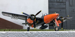
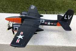
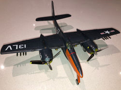
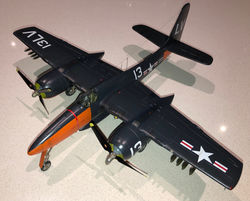
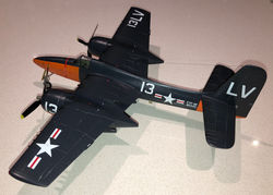
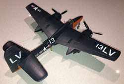
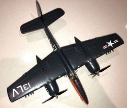
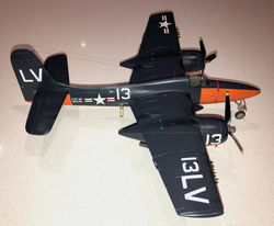
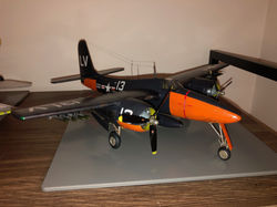
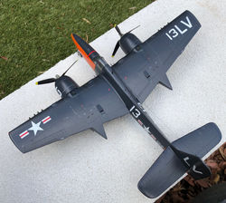
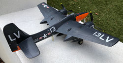
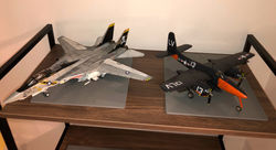
Grumman F7F-3P Tigercat
VMP-354
MCAS Cherry Point, NC, 1949
1/48 Italeri
Why this plane?
All of my previous model planes were jets, and I wanted to try my hand at building a propeller plane. When I saw pictures of the Tigercat I knew I found my subject. Such graceful lines!
The Italeri kit gives you decals for 6 versions of the F7F-3. I decided to build the photo reconnisance version (-3P) from a squadron based in the US in the years after World War 2 because of the nice orange coloured details in the nose, engine nacelles and back end. I thought this scheme would add to the challenge. I think the result was worth it.
I have no idea if photo reconnisance Tigercats ever carried bombs and rockets, but being a Marines plane I guessed they would tend to keep the capacity to wreak some damage "just in case". Anyway, you could also imagine this as a plane from an alternate reality in which VMP-354 deployed to Korea.
What was added
No purchased upgrades, but I had some ideas on how to make the R-2800 Double Wasp engines look a bit more realistic, by combining the Italeri-provided parts with some home-scrounged items. Thus, some details in the engines were scratch-built. I am pretty happy with the result, and have added a section below to explain what was done.
Notes and lessons learned
Another very nice kit from Italeri, real value for money. The fit is fantastic. Even potentially problematic steps like getting the angle of the dihedral wings correct were made easy by having features that limit the degrees of freedom in the construction (i.e. no possible ways fo getting it wrong). This resulted in an enjoyable, drama-free build.
The weathering was kept relatively light. The Vallejo dark sea blue was painted on top of a fine layer of Tamiya chrome silver. This allowed me to create the effect of worn out paint by running a fine scriber, lightly, along the recessed panel line. An even subtler effect was achieved in other places by running a fine pacer along the panel lines, as I did for the F-14A. This was great, for example, to make the orange parts look more realistic, but also helped create the effect of joined panels in the dark sea blue parts. Dry brushing silver metallic paint and drawing fine lines with a Prismacolor PC949 (silver) pencil helped create the effect of worn out paint along the leading edges of wings, engine cowlings, nose and stabilisers. Additional weathering was done using Tamiya weathering master sets B and D, particularly to create the impression of burned and dirty paint behind the engine exhausts and guns.
This was my first experience with the Vallejo acrylic varnish, which was used for the final coat. I decided to try this instead of Tamiya TS-79 because of the problem I had with the Tomcat, when what was supposed to be a final sealing coat resulted in cracking paint and a lot of subsequent sanding. I am happy to report that the Vallejo varnish was excellent, once you get the dilution right. Don't try to use it straight out of the bottle, even if the instructions tell you that you could do so; it is too thick. I got the best results by mixing 4 parts of varnish, 3 parts of airbrush thinner, and 1 part of water. I also played with the ratio of satin and matt varnish to get the right amount of "shine" from the surfaces. In this model I used 3 parts of satin to 1 part of matt.
The cockpit has a fair bit of detail straight out of the box. everything clicked together beautifully, and it comes with instrument panel and seatbelt decals. See below for photos.
This particular plane (BuNo 80442) had a second, finer aerial behind the main mast, which I think was part of a VHF navigation system. This was made from fine hobby wire and then painted black. The aerial leads were made from fishing line, and also painted black.
The model does not come with the ventral recognition lights. After considering complicated alternatives (like cutting and sanding to shape tiny bits of clear sprue), I tried something simple: three little blobs of Micro Kristal Klear glue. These, after drying, became transparent, and could be covered with clear red, green and yellow Tamiya acrylic paint. The result seems convincing to me.
Problems circumvented
Before I started this model I tried to learn as much as possible from web reviews like this, this, or this one. Thus, I started well warned that this plane required an enormous amount of nose weight to sit straight. I confirm that this is, indeed, something you need to be prepared for. I included a section below show below to show exactly how much weight I included to make this plane stable without having to resource to the parts provided in the kit to prop the tail up (a barrel and ammo box).
Another warning I got from previous web reviews is about the construction of the undercarriage. The parts are very delicate, and could break easily in the process of trying to fit them inside the nacelles. I also found that the diagrams for assembly of the main wheel gear are not very clear in the instruction sheet. I include below some pictures of intermediate steps that hopefully will help clarify how the parts should be joined to build the undercarriage. As a last point: definitely, add weight to the front of the nacelles before you click the main landing gear in place, and wait to glue the wheel doors after the undercarriage is all assembled.
The instructions are misleading with respect to assembling the rockets (HVAR). Each HVAR comes in two parts, which need to be put together: a) the main body combined with the warhead as a single piece, attached to an underwing pylon, and b) the back end of the rocket with the cruciform fins. The instructions indicate that you should align the fins with the pylons, but if you do this you will find that there is not enough room to separate the HVARs from each other, when you try to attach them to the bottom of the wings. This, and a (sadly, late) check of reference pictures (like this one) resulted in me having to clip each rocket in order to rotate the fins, before cementing them back.
The main aerial mast comes attached to one of the halves of the fuselage. It is very fragile, and broke off almost immediately as I started to build. Re-attaching it to the top of the fuselage (after reinforcing with a bit of fine wire, inserted through a pin hole) was pretty much the last thing I did, together with attaching the pitot tube under the left wing and the retractable steps. Leaving these easily breakable bits to the end saved me a lot of trouble.
And, finally the decals: this kit continued my love/hate relationship with Italeri decals. The decals are actually very nice, sharply printed and easy setting (given reasonable amounts of Microset and Microsol). It would have been perfect if it wasn't for the fact that the instructions can be best described as an approximation: the illustrations don't match the actual kit in terms of illustrated detail, like panel lines and proportions, leaving a lot of room for interpretation. Some decals look too big in comparison with the drawings, some too small. I still don't know if the drawings were correct and the decals were of the wrong size, or vice-versa. But I could not find any surviving photos of this plane, and the markings seem reasonable in comparison with those in other Tigercats at that time.
 Pilot seat 2.jpgThe Italeri-provided seat out of the box |
|---|
 Pilot seat 1.jpgThe Italeri-provided seat out of the box |
 Cockpit partial 1.jpgThe Italeri-provided seat out of the box plus some side detail |
 Instrument panel.jpgTh italeri-provided instrument panel decal |
 Cockpit partial 2.jpg |
 Cockpit partial 3.jpgThe Italeri-provided seat out of the box plus some side detail |
Building the cockpit
These images give you some idea of what type of cockpit detail you can get out of the box. The seatbelts are decals, to which I applied too much Microsol, I think. They look painted onto the seat instead of lying there naturally. A good decal is provided for the main Instrument panel.
 nose with weights.jpgThis is how much weight I added to the nose before joining the fuselage. These are all line sinkers, sometimes cut to fit in the restricted space |
|---|
 undercarriage weights.JPGAnd, more line sinkers glued with cyanoacrylate behind the engine nacelles |
 undercarriage step 1.JPGThis is how the different pieces of the undercarriage are meant to go together. I found the instructions not very clear, which resulted in a lot of trial and error. |
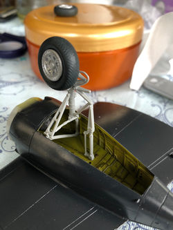 undercarriage step 2.JPGStep 2, now with the wheel in place |
Weights and undercarriage assembly
The first two photos show how much weight I added (these are all line sinkers, sometimes cut so that I could fit more of them in the small space).
The other two photos show how the different components of the undercarriage should fit together. The instructions were not very clear in this respect so it took me some trial and error.
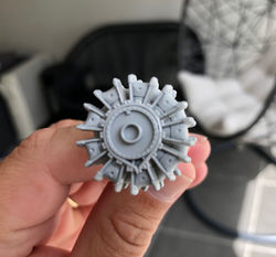 1 basic engine from the box.JPGThis is the basic engine provided in the Italeri kit |
|---|
 2 engine step 1.JPGStep one: added Inter-ear drain tubes |
 3 All pipes added.JPGA more advanced step, where the spark plug leads and scavenge return oil tubes had been added. |
 4 engines ready.JPGComplete engine, including magneto and distributors. This front part is pretty much original Italeri except for the high tension leads linking magneto to distributors. |
 5 engines in place.JPGComplete engines attached. |
 6 engines in place 2.JPGAnother view of the engines in place. |
 7 engines in place 3.JPGFinal view, with cowlings positioned. |
Double Wasp Engines
The engines provided were pretty basic. My reference pictures suggested a lot extra cables and pipes existed in the real thing, so I proceeded to add the ones that I could, using a mixture of hobby wire and heavy fishing line, all glued to pin vise holes using cyanoacrylate gel. I focused on the front part, which in the end is all that can still be seen through the engine cowling.