 |  |  |  |  |  |  |
|---|---|---|---|---|---|---|
 |  |  |  |  |  |  |
 |  |  |  |  |  |  |
 |  |  |  |  |  |  |
 |  |  |  |  |  |  |
 |  |  |  |  |  |  |
 |  |  |  |  |  |  |
 |  |
Click on a picture in the gallery above to see a full resolution image, or to navigate manually
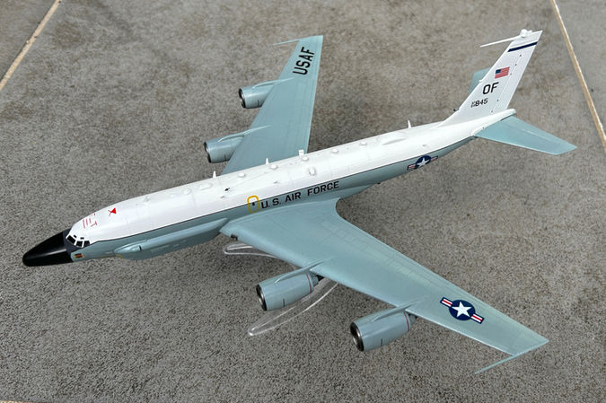
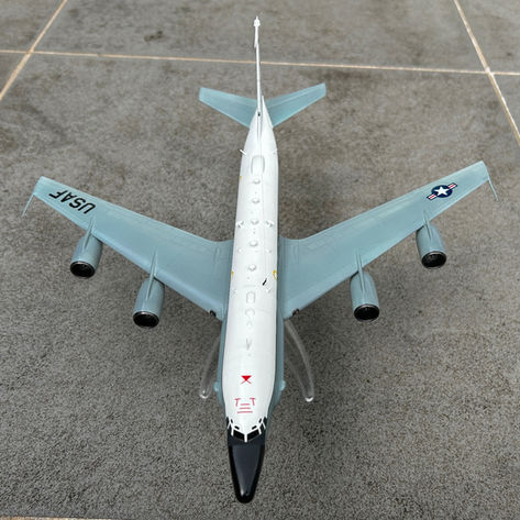
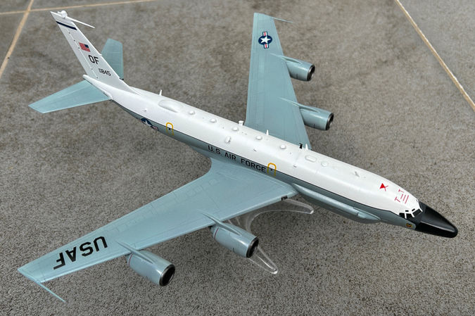
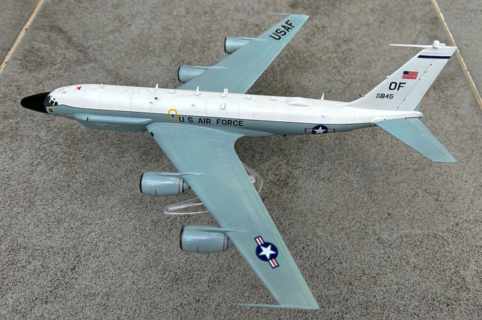
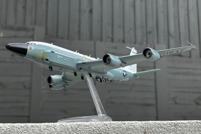
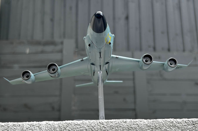
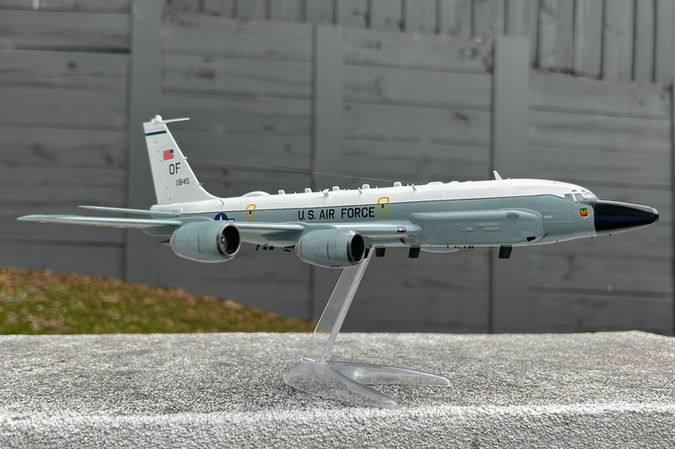
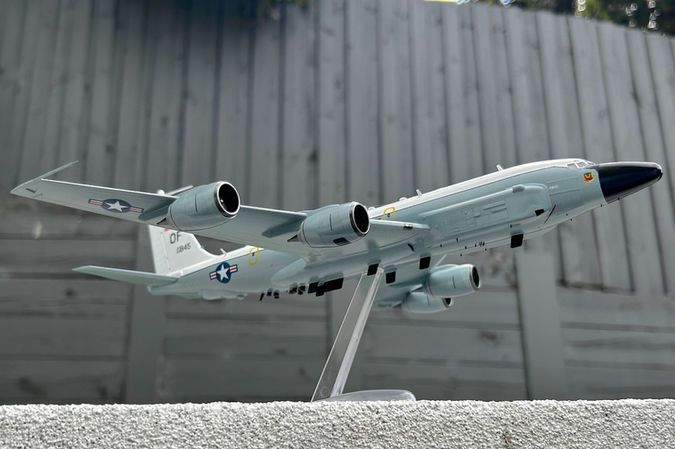
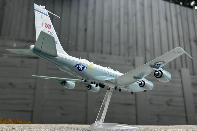
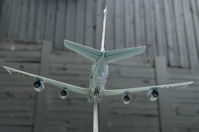
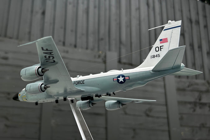
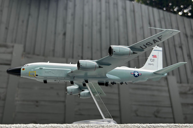
Boeing RC-135V/W Rivet Joint
55th Wing, Air Combat Command
RAF Mildenhall, May 2008
Why this plane?
The C-135 family of planes has been flying for longer than I have been alive, and continue to look great after all these years. When I heard that Roden was going to release a newly tooled kit of the "Rivet Joint" (RC-135V/W, a heavily upgraded signals intelligence platform) I felt that it would be a challenging, and somewhat unique modelling subject (I mean, look at all those antennas!).
What was added (or changed)
-
I needed to outsource some decals, including, most notably, the black lines that separate the white and grey parts of the fuselage. The decals that come with this kit are, for the most part, borderline usable, and some are truly awful (special mention to the yellow outlines for the doors and portside instrument bay). In general, all lines are too thick given the scale. In addition, some prominent markings visible in the reference images are not included. I did the best I could using bits rescued from the spares box, but in retrospect should have invested in an aftermarket set. In summary, decals continue being the Achilles' heel of Roden kits (see also my B-36D build report).
Decal issues: Top left: The terrible yellow outline of the instrument bay, which failed to settle even after many applications of MicroSet and MicroSol, and kept this mottled appearance despite my best efforts. Unfortunately, I had no spare yellow line decals left from previous kits, so ultimately this had to be painted over with Tamiya XF-3. Top right: The decals for the red lines in the cowlings are way too thick in comparison with reference pictures, so also here bits from the spares box had to be used. Bottom: some examples of additional markings that were missing from the kit (red arrows).
-
RC-135s are covered in antennas, and part of the modelling challenge is to try to capture faithfully the "busy" look.
-
The Roden kit comes with most of the larger antennas, but some appear overscaled. I ended up substituting many of them with bits of photo etch left over from other kits, cut to appropriate size.
-
Smaller antennas, such as those under the nose and fuselage, and some of those along the dorsal spine, are not included at all, so again I cut tiny bits of photo etch to represent.
-
Antennas added: Left: One of the new additions, made from leftover photo etch. This particular antenna pair (FD1/ FD3/ UHF3) was not included in the kit. Other antennas along the dorsal and ventral spines were included, but were substituted with photo etch anyway, for a more accurate scale. Right: Some of the tiny antennas added along the bottom of the fuselage.
- The biggest letdown in this kit was the fact that some of the parts needed for the "mushroom" antennas were malformed. You simply cannot have a Rivet Joint without these looking good! My solution was to get some Evergreen sheet, and use an appropriately sized hole punch to create some substitutes.
Plastic injection fails: Left: One of the sprues, showing how parts intended to become antenna "caps" were malformed (red arrows). Right: My solution involved some black Evergreen, and a hole puncher.
-
Having decided to represent the plane in flight, I closed the wheel bays, and repurposed an old Airfix stand for the purpose.
-
Rigging the aerial was done using a human hair.
Notes and lessons learned...
This is a Roden kit. You don't decide to do one of these because you want perfectly fitting parts, and refined engineering. You do it because this manufacturer provides reasonably accurate, reasonably priced kits of unique subjects. Having said that, the overall quality was better than what I found in the slightly older B-36D kit. For example, fitting of the wings and horizontal stabilisers required only a tiny bit of filler, and even the decals appeared to have the colours almost in register with each other. I hope that this indicates that Roden is on its way to improvement.
Thus, I don't want to sound too negative (I DO appreciate Roden kits!). My notes below are mostly intended to call attention to some features which may be worth knowing about, if you plan to build this model.
-
As one would expect, this was all about the antennas. Surprising no one, these break all the time as you turn the model around to paint, place decals, etc. There is no way around that I could find, since delaying the installation to the end would probably have meant unnatural transitions in painting. As shown below, I installed most antennas just prior to priming. Towards the end, the constant fixing of broken bits made me feel like I was doing 3 steps forward, 2 steps back, all the time. At least this gave me plenty of opportunities to substitute the thick plastic antennas with more suitably sized photoetch ones.
-
The recessed panel lines were useful, but in most places a bit too deep for scale. I ended up sanding them in most places, to leave just a suggestion, and slightly pre-shading with a lead pencil before applying the final coats.
-
Many of the antennas are moulded into the fuselage halves. This creates a problem because there is a prominent seam line that needs to be sanded (see under Construction pictures). This could have been easily avoided if the antennas were provided as separate parts, to be added after the fuselage was joined. There is no easy solution to that one, other than getting sanding sticks of different sizes and shapes, and trying to go around the many bumps.
-
The way the engine intakes are provided causes a devilish problem if you want to sand them to a smooth finish (as you do, for a metallic part). Whoever in the Roden headquarters decided to leave those cross braces inside needs some talking to...
Engine intakes: Top left: The original part, with thick cross-braces inside. Top right: After using the sprue cutter, a lot of plastic is left inside. Even after thinning this with a scalpel, big bumps are left. Bottom left: The only solution is to get sanding sponges bent into little strips, and keep them going 'round and 'round. Bottom right: A smooth finish can be achieved, but this takes a disproportionate amount of time...
-
Painting the top of the fuselage was done with SMS white, after pre-shading with lead pencil. Finding a visual match for the grey in the wings and bottom fuselage was not so simple. In part, this is because the perception of the grey in the RC-135s changes so much depending on the illumination conditions. I started with AK 3rd gen 11867 (ADC Grey), and added some variation using thin coats of Mr Color 337 (Greyish Blue), Mr Color 118 (RLM78 Light Blue) and Vallejo 71335 (Flanker Light Grey) over selected panels.
-
This is probably also a good place to mention that the decal instructions contain some glaring errors, including for example the suggested placement of the USAF roundels in the wings, and of the tail markings. Fortunately, there are many good pictures of "Rivet Joints" online, so this was just a mild inconvenience.
-
Another minor issue not covered in the Instructions: They represent the wingtip antennas fitting on notches which actually don't exist in the provided parts. You have to cut your own.
Click on a picture to see a full resolution image, or to navigate manually
In summary...
Kudos to Roden for providing us with a kit of such an interesting subject. It was challenging at times, but overall a fun project. If only they could get someone else to print their decals...
Click on a picture to see a full resolution image, or to navigate manually
Construction images

Parts included in the Roden 1/144 Rivet Joint kit

The engraved panel lines are sharp, but a bit too deep for a 1/144 model

After a layer of SMS clear gloss, the decals were added. The ones for the vertical stabiliser were adequate. The red arrows point some detail I added, based on reference images.

Parts included in the Roden 1/144 Rivet Joint kit
Click on a picture in the gallery above to see a full resolution image, or to navigate manually
-
Parts included in the Roden 1/144 Rivet Joint kit.
-
The engraved panel lines are sharp, but a bit too deep for a 1/144 model. They had to be softened a bit by sanding.
-
The fit is OK, but that prominent seam line requires one to sand carefully around all the bumps. Not surprisingly, the FD antenna near the front was one of the first to break. Note also the amount of flash in the cockpit area.
-
One of the first jobs is to fit the windows, which are provided as clear parts that are glued inside the fuselage. I used Micro Krystal Klear for that.
-
After joining the fuselage, patience is required to smooth the seam without destroying the antennas. Here, Vallejo putty is still visible towards the back.
-
Preparing the wings was a relatively easy step. Just a small bit of filler, and sanding. Once assembled they fit easily with the fuselage.
-
The front windows are provided as part of a larger clear part (dry fitted here). The fit is not too bad, but still requires significant sanding to smooth the transition. Note how the front antenna has already been broken…
-
After a few cycles of sanding, the clear part enclosing the cockpit has been integrated, and the windows masked. Fitting the cheeks fairings was a surprisingly easy step, given a near-perfect fit.
-
The fit between the engines and the wings is bad. This shows the initial attempt to use filler to ease the transition. Many more cycles of filling and sanding were required after that.
-
Finally, something looking like a RC-135 is taking shape. Primer/ filler helps smooth the transitions. I used Mr Primer Surfacer 1000 here.
-
Painting the upper and front fuselage. Mostly SMS white, with touches of X-1 for the front radome, and XF-1 for the antireflective panel. No dramas unmasking the windows (this time).
-
After masking the white and black surfaces, all that is left needs to be airbrushed with light grey. The model is shown here after an initial coat of AK ADC grey, and panel line highlighting with a pacer.
-
Other grey tones were lightly airbrushed after masking selected panels. This added some variety to the grey, giving a mild impression of weathering.
-
After a layer of SMS clear gloss, the decals were added. The ones for the vertical stabiliser were adequate. The red arrows point some detail I added, based on reference images.


.jpg)


